It is known fact, that design of headphone amplifier differs from the speaker amplifier due to notable difference in the required power. The other requirement is the ability to handle loads in range from 32 to 600 Ohms. There are tons of various designs available: tube based, BJTs or MOSFETs based, with or without global feedback, battery or mains powered, etc., etc.
I'm also a user of self made headphone amplifier for over twenty years now. During this time it was modified multiple times and moved to various enclosures. But recently, it was noticed, that electrical part wasn't modified at all for last two years, so I've decided to place it into new case in hope to make it more usable. The case was salvaged from the old SAT receiver kindly donated by a friend:

As one can see, it have (from left to right): power/standby indicator, four buttons, remote control eye, the phone jack, display and a big knob. Well, the knob isn't that big, but just because my cat stole the big black knob and I'm still trying to find it. The rear side have power connectors, mains switch and input connectors:

From outside, it looks like an ordinary device, but lets go inside:

Now, it is more interesting - seven(!) PCBs on the chassis and yet another two on the front panel. Obviously, this is not a minimalistic design at all. Lets take a closer look.
There are Russian saying, “Every theater begins with a hanger”, and each good amplifier starts with a good power supply. But wait, the PSU on the picture is a switched one! It is definitely will deserve admonition from some purists. In early incarnations, this amplifier had a transformer based PSU with linear post regulators. But later, it was replaced to a switched PSU with primary side regulation which allowed to dissipate much less heat in the linear post regulators. There was no difference noted in both, subjective and objective tests.
Power amplifier board located to the right of heatsinks of linear regulators. Each channel have four NE5532 amplifiers placed in parallel which gives a plenty of power to drive even low impedance loads. It have OP97 based integrators to maintain zero DC offset on the output. The small board nearby is a DC-protection.
The board near input jacks is a three channel input selector, the attenuator and CS3310-based volume control. Attenuator allows one to keep signal specifications within CS3310 limits. The whole board are controlled using I2C bus, the conversion is done by MCU (which is located on the bottom side).
The board in the bottom right corner is a bass/treble shelve tone control. This is the controversial feature, but IMHO, this feature is invaluable because each headphones have its own frequency response and human ear also tends to change its sensitivity to high frequencies over the years. The board also digitally controlled over I2C bus.
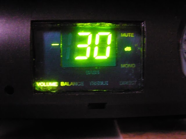
Finally, the small board on top and near the PSU is the control unit, which handles all events from buttons, encoder and DC protection. It also puts information on display:

There are plans to implement remote control of amplifier, but currently it is not required because all controls can be reached by hands.
Thorough reader may notice that one channel of the input selector is not connected to anything, and there are two holes on the rear side without connectors. Well, this reserved for a DAC, which currently lives in its own case, but this is a different story.
I'm also a user of self made headphone amplifier for over twenty years now. During this time it was modified multiple times and moved to various enclosures. But recently, it was noticed, that electrical part wasn't modified at all for last two years, so I've decided to place it into new case in hope to make it more usable. The case was salvaged from the old SAT receiver kindly donated by a friend:


From outside, it looks like an ordinary device, but lets go inside:

Now, it is more interesting - seven(!) PCBs on the chassis and yet another two on the front panel. Obviously, this is not a minimalistic design at all. Lets take a closer look.
There are Russian saying, “Every theater begins with a hanger”, and each good amplifier starts with a good power supply. But wait, the PSU on the picture is a switched one! It is definitely will deserve admonition from some purists. In early incarnations, this amplifier had a transformer based PSU with linear post regulators. But later, it was replaced to a switched PSU with primary side regulation which allowed to dissipate much less heat in the linear post regulators. There was no difference noted in both, subjective and objective tests.
Power amplifier board located to the right of heatsinks of linear regulators. Each channel have four NE5532 amplifiers placed in parallel which gives a plenty of power to drive even low impedance loads. It have OP97 based integrators to maintain zero DC offset on the output. The small board nearby is a DC-protection.
The board near input jacks is a three channel input selector, the attenuator and CS3310-based volume control. Attenuator allows one to keep signal specifications within CS3310 limits. The whole board are controlled using I2C bus, the conversion is done by MCU (which is located on the bottom side).
The board in the bottom right corner is a bass/treble shelve tone control. This is the controversial feature, but IMHO, this feature is invaluable because each headphones have its own frequency response and human ear also tends to change its sensitivity to high frequencies over the years. The board also digitally controlled over I2C bus.
Finally, the small board on top and near the PSU is the control unit, which handles all events from buttons, encoder and DC protection. It also puts information on display:
There are plans to implement remote control of amplifier, but currently it is not required because all controls can be reached by hands.
Thorough reader may notice that one channel of the input selector is not connected to anything, and there are two holes on the rear side without connectors. Well, this reserved for a DAC, which currently lives in its own case, but this is a different story.